Before you start: the model and tools
You will make one solid body from a rectangle on the XY plane. The sketch controls the width and height; the extrusion gives that flat profile its depth. Changing a driving dimension later changes the resulting solid, which is the central idea of parametric modeling.
Use a desktop browser with hardware acceleration and a mouse. No installation or account is required for the online exercise. Keep this guide beside the editor, enter dimensions in millimeters, and expect a final volume of 40 × 30 × 10 = 12,000 mm³.
Workflow and screenshots checked in SolidCraft v0.15.0 on 2026-10-18. Geometry was created through the upstream browser command API; the UI uses the same engine commands. Button positions can change in other releases.
Open the SolidCraft web editor
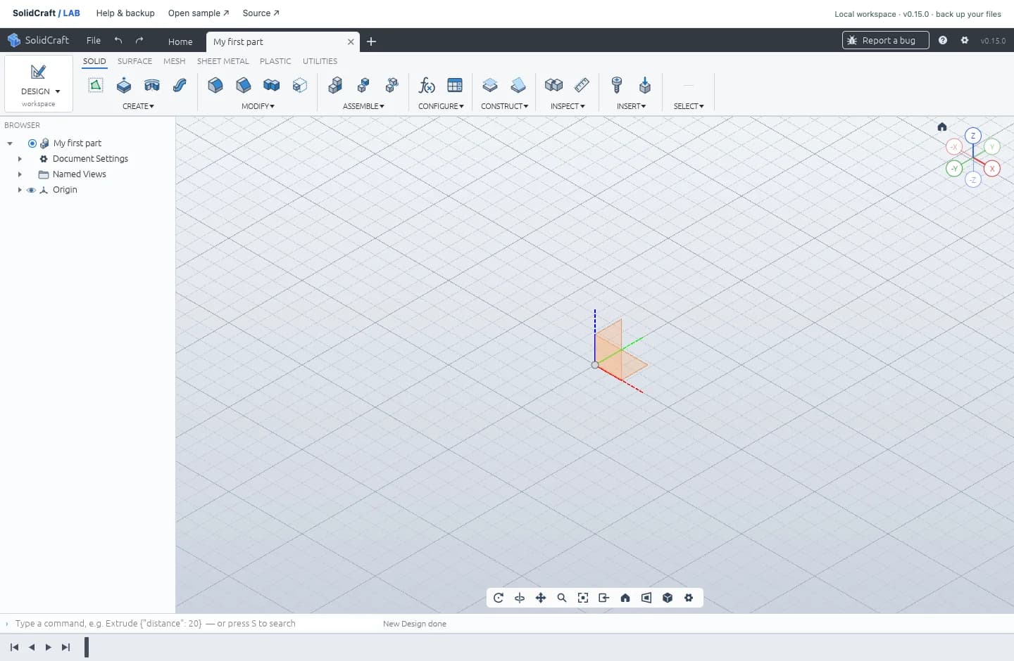
Open the editor in another tab and create a New Design. Name it “My first part.” Keep this guide open beside the editor so you can move between the two.
Create a rectangle sketch on the XY plane
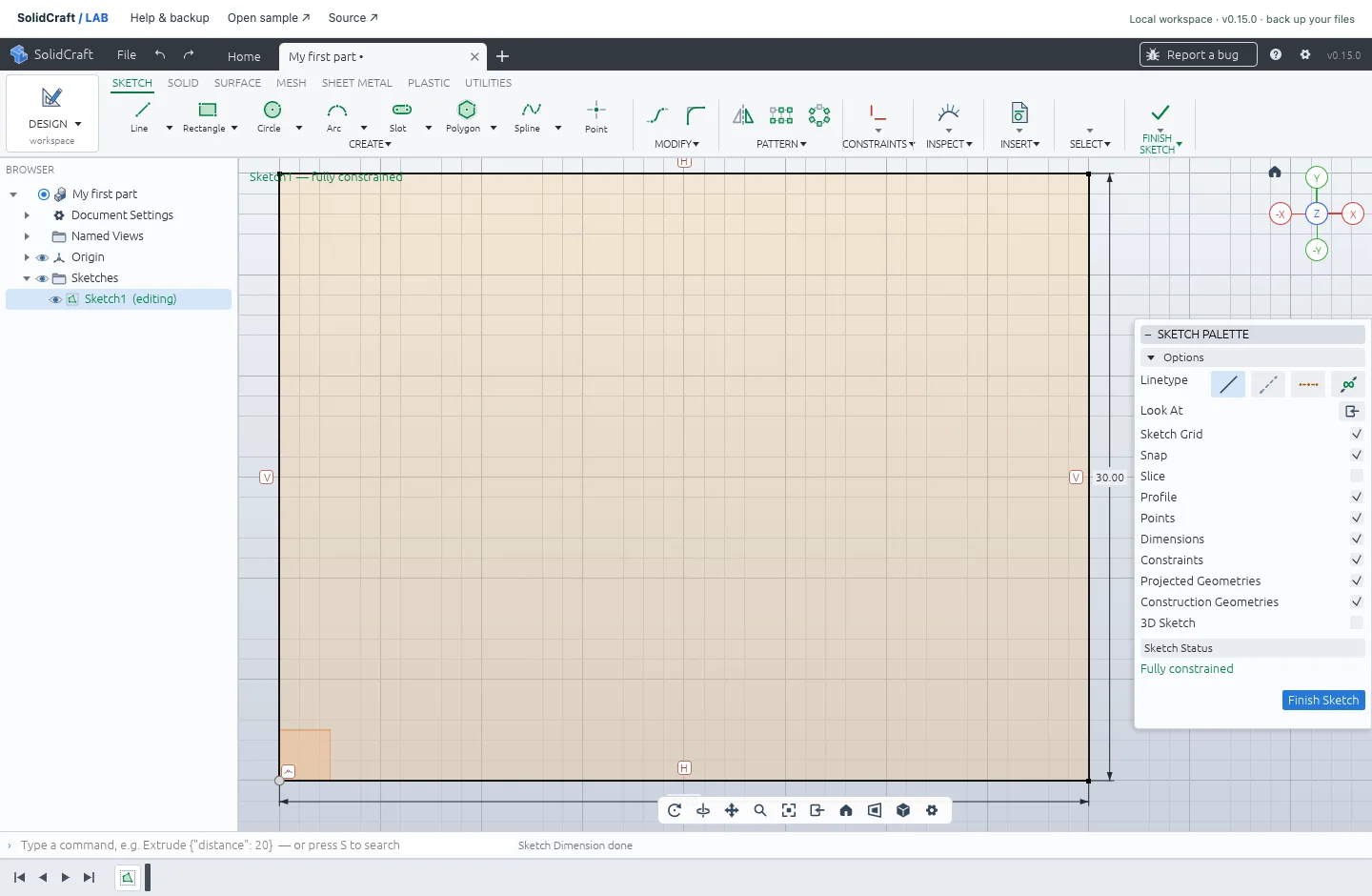
Create a sketch on the XY plane. Choose 2-Point Rectangle and snap the first corner to the origin, then place the opposite corner in the positive X and Y directions. Aim for roughly 40 mm across and 30 mm high; you’ll set the exact size next. Press Esc to leave the rectangle tool.
![A real XY sketch with a rectangular profile. The sample uses corners [0, 0] and [40, 30].](/_next/image?url=%2Fimages%2Ftutorial-sketch.webp&w=3840&q=75&dpl=dpl_54YoCTjpR6HSjCQdDXdj1AjkG5HB)
Constrain the sketch to 40 × 30 mm
Press D for Sketch Dimension, click the bottom horizontal edge, type 40 mm, and press Enter. Repeat for the right vertical edge with 30 mm. In the supplied example these driving parameters are d1 and d2; names in your own design can differ.
Extrude the profile into a 3D solid
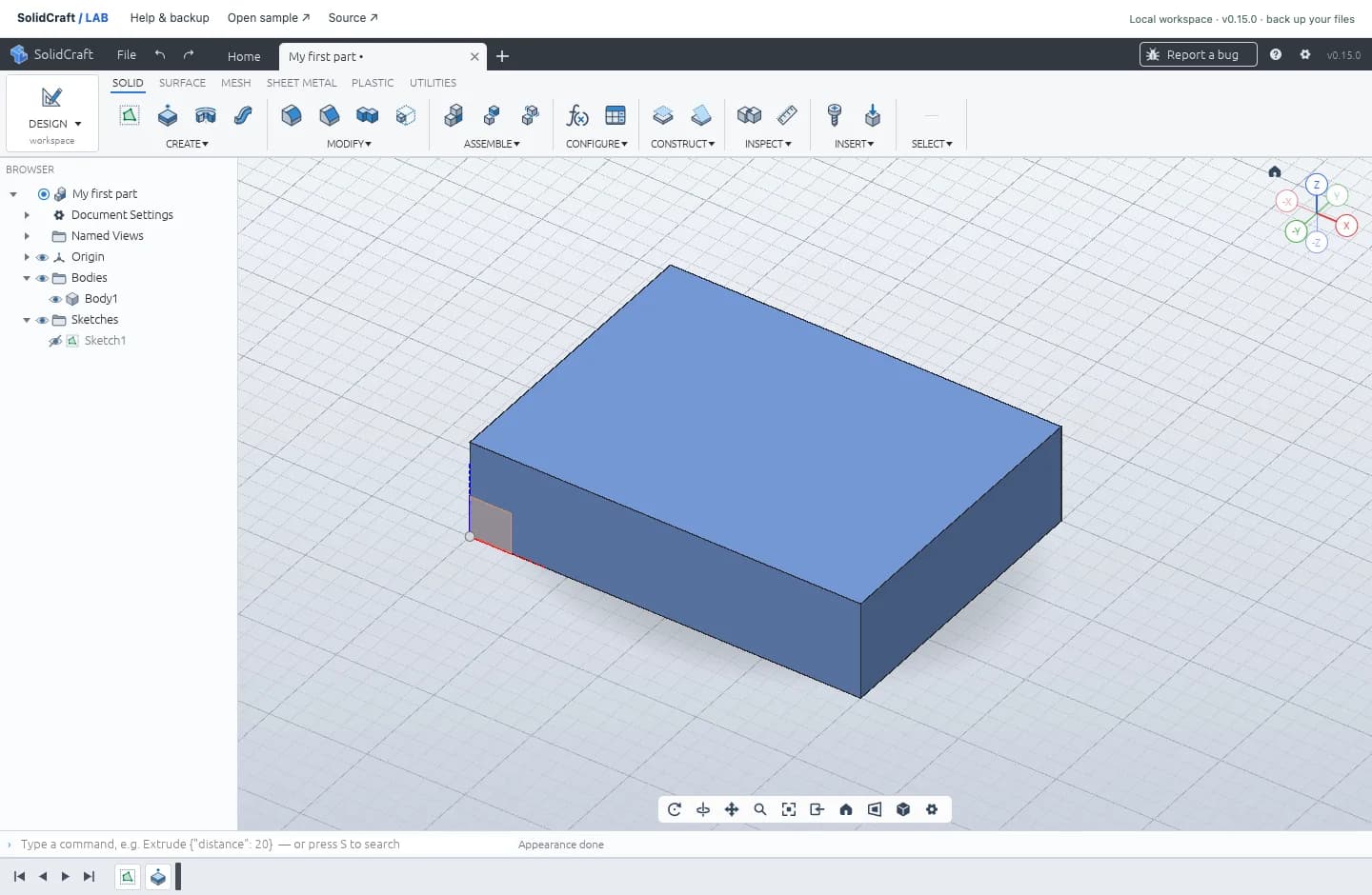
Finish the sketch. Choose Extrude, select the rectangular profile, and set the distance to 10 mm. Confirm the operation and switch to an isometric view to inspect your part.
Save and reopen the .solidcraft design
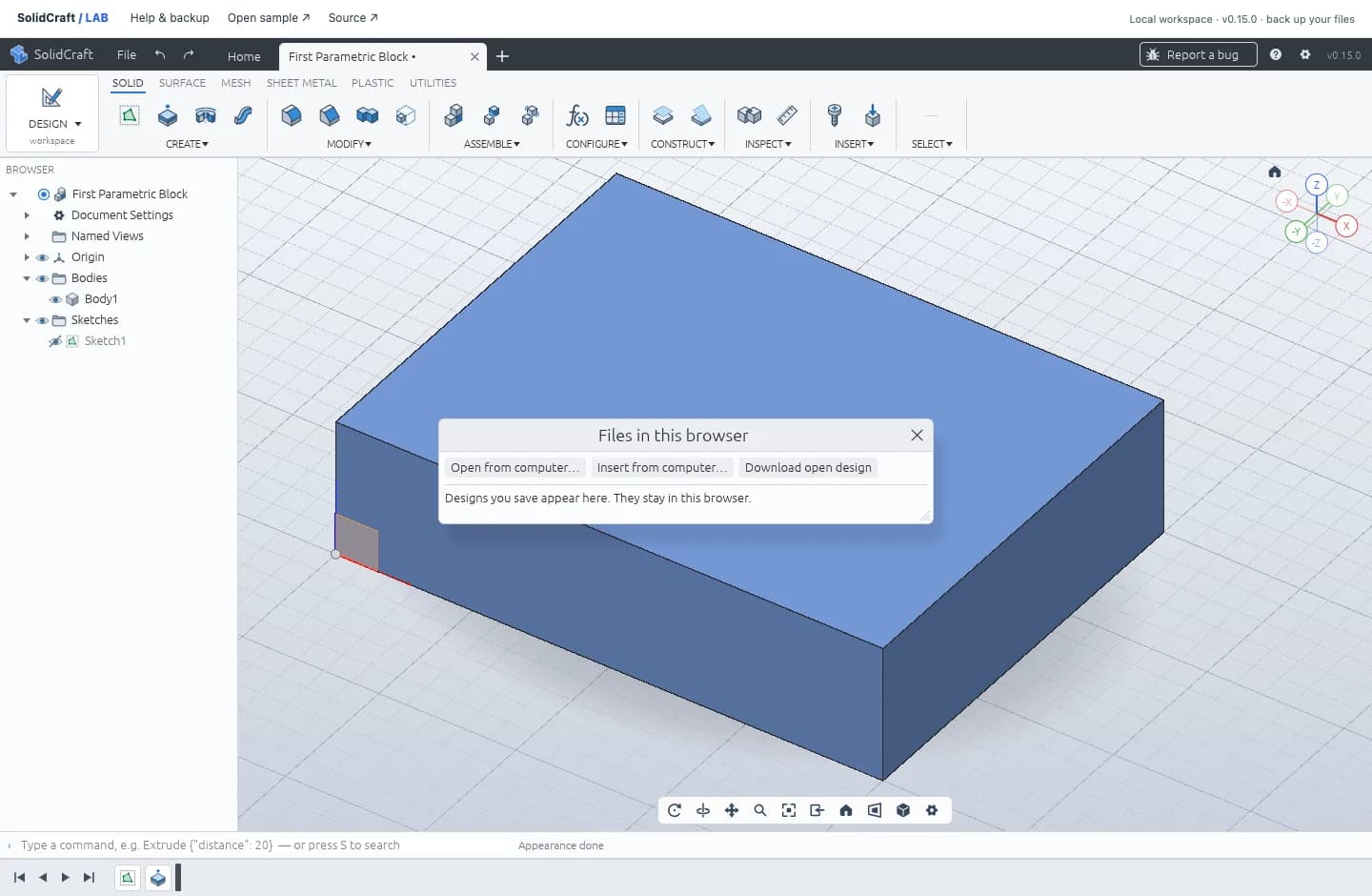
Save the design in the browser, then use File → Open… → Download open design to download a native .solidcraft backup. To check the backup, choose Open from computer… in the same panel and select the downloaded file, or drop it onto the CAD canvas. Your sketch and extrusion should rebuild.
Check a parametric dimension change
In the SOLID toolbar’s CONFIGURE panel, open Parameters (Change Parameters). Find the parameter that drives the 40 mm width and change it to 50 mm; it is d1 in the supplied example. The other sketch dimension stays at 30 mm and the extrusion stays at 10 mm, so the rebuilt volume should be 50 × 30 × 10 = 15,000 mm³. This checks that the dimension drives the model, rather than simply labeling a fixed shape.
Undo should return the block to 12,000 mm³; redo should restore the wider version. Keep Sketch1 and Extrude1 in the timeline so you can return to the construction. Download the modified native design again when you want to keep those changes outside browser storage.
If there is no solid, revisit the closed profile and extrusion selection. If a dimension conflicts, inspect the sketch’s existing constraints before adding another. The finished parametric block gives you a working reference for the sketch, feature tree and expected dimensions.
Ready to compare your work with the verified model?
Explore the finished example