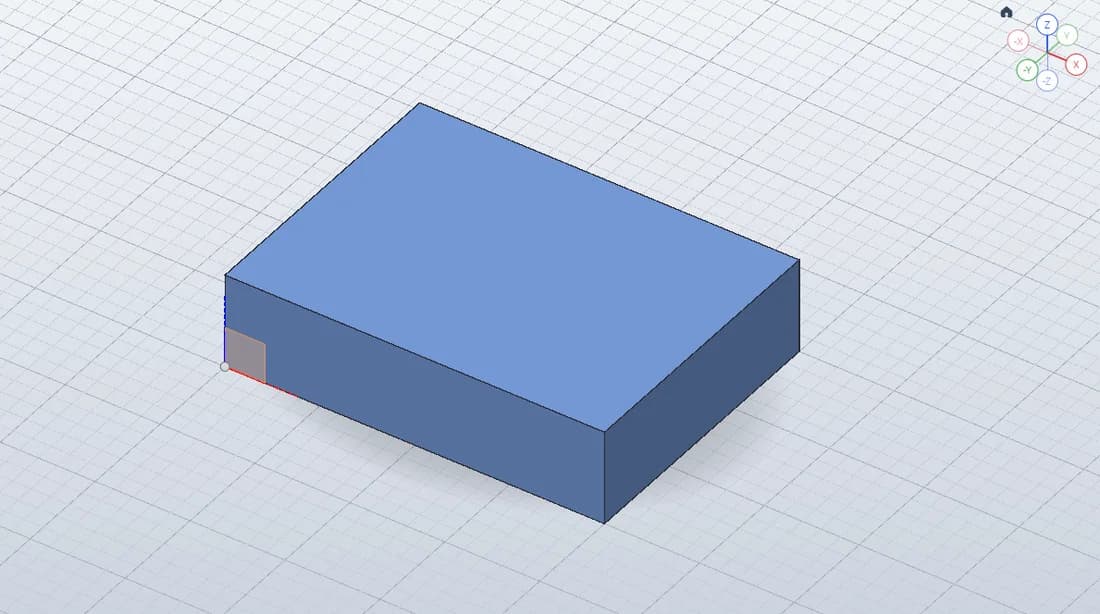
Edit the parametric block in SolidCraft
The sketch has two driving dimensions and zero remaining degrees of freedom. Edit d1 or d2 in Change Parameters to see the extrusion rebuild.
- DIMENSIONS
- 40 × 30 × 10 mm
- MEASURED VOLUME
- 12,000 mm³
- EDITABLE FORMAT
- .solidcraft native design
- CHECKED IN
- Web editor v0.15.0
How the parametric block is constructed
Sketch1 is a rectangle on the XY plane, starting at the origin and extending 40 mm in X and 30 mm in Y. Two driving dimensions, d1 and d2, define the footprint. The verified sketch has zero remaining degrees of freedom, so its intended size and position are fixed by the constraints.
Extrude1 gives that closed profile a depth of 10 mm. The result is one solid body with six planar faces. This small model makes the feature relationship easy to inspect: the rectangle defines the cross-section, the extrusion defines the depth, and changing a sketch dimension changes the resulting body.
Change a dimension and check the rebuilt solid
- Open the example and find Sketch1 and Extrude1 in the feature timeline. Inspect the original 40 × 30 × 10 mm dimensions before making a change.
- In the SOLID toolbar’s CONFIGURE panel, open Parameters (Change Parameters) and change
d1from 40 mm to 50 mm. With the other dimensions unchanged, the volume becomes 50 × 30 × 10 = 15,000 mm³. - Undo the dimension change to return to the original 12,000 mm³ block, then redo it. The sketch and extrusion remain editable throughout the exercise.
- Download a new native copy after changing the part. A file you downloaded earlier remains a separate snapshot of the older design.
Verified dimensions, volume and native-file recovery
The original solid measures 40 × 30 × 10 mm, with a volume of 12,000 mm³. In our browser check, changing d1 to 50 mm produced 15,000 mm³; undo and redo restored the expected versions. These checks confirm that the example has working parametric geometry.
We also downloaded its native .solidcraft file and imported it again, rebuilding the same 12,000 mm³ solid. Saving to browser storage, reloading the page and reopening that saved design preserved the geometry. These checks used the v0.15.0 browser build; the verification notes describe the tested environment.
Save your modified SolidCraft design
Use File → Open… → Download open design to keep an editable .solidcraft backup. Browser Save keeps a local browser copy; it does not update a previously downloaded file. Keep the native design when you want to revisit the sketch and feature history, even if you also export geometry for another application.
For the next exercise, explore the mounting plate with four through-holes. Its inner profiles add another sketch-to-solid construction to inspect.
Created and measured in the browser on 2026-10-18. The screenshot shows the actual model. Dimensions are in millimeters; example geometry is provided for learning.